
MONICA (MOnochromatic Image CAmera) is an instrument for the 0.8 m telescope at Wendelstein which allows broad- and narrowband direct imaging by using a LN2 cooled CCD detector.
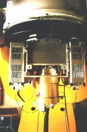
MONICA at the 0.8 m telescope
The camera housing is a square metal box, measuring 40 cm in diameter, constructed out of 10 mm thick aluminium plates. The 15 mm thick telescope flange is removable for easy access to the instrument interior and is fixed to the box by screws. The structure is designed for flexure of less than 5 um (zenith to horizon). An aluminium plate with integrated cooling pipes is mounted inside the housing. The liquid coolant is provided by a heat exchanger which is located in the control room of the telescope. The filter unit, the offset guiding camera, and the broadband filter wheel are fixed to the cooling plate. That allows the removal of the heat dissipated by these units (stepping motors and thermoelectric coolers). The CCD cryostat is mounted at the bottom of the housing while two electronics chassis are attached on both sides of the instrument.
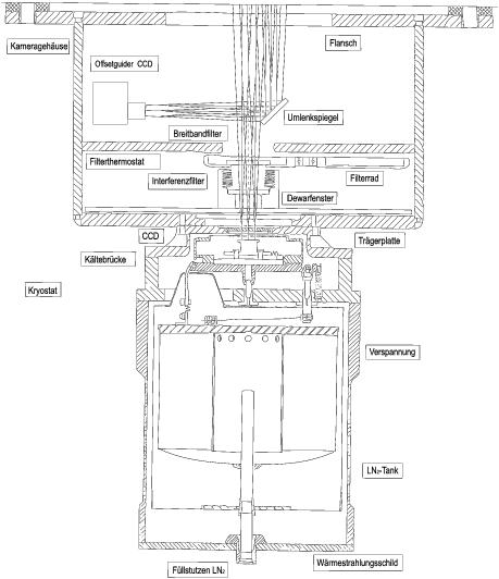
Schematic draft
A commercial CCD system ST-7 from SBIG is used for offset guiding. It is mounted on a radial translation stage which in turn may be rotated by 270 degrees on an azimuth drive fixed at the center of the cooling plate. A central opening of 50 mm in the azimuth drive passes the telescope beam down to the cryostat. A motor driven adjustable diagonal mirror on the radial stage images a 1:1 subfield onto the guiding CCD and allows for focussing and for compensation of the focal plane curvature. This arrangement offers the use of a 2.4 arcmin x 1.6 arcmin field out of a region of 40 arcmin in diameter for autoguiding.
The filter unit allows to insert several filter boxes. Each can hold a single filter with 50 mm diameter and with a maximum thickness of 7.5 mm. The boxes can be manually exchanged via an opening in the instrument housing. They are electrically encoded for software identification of the inserted filter. Five of these boxes are available and can be loaded with the following narrowband interference filters:
| Wavelength | Bandwidth | Peak Transmission |
|---|---|---|
| 406.0 nm | 7.0 nm | |
| 468.40 nm | 0.8 nm | 30 % |
| 480.00 nm | 5.4 nm | 35 % |
| 485.82 nm | 0.8 nm | 35 % |
| 500.36 nm | 0.83 nm | 40 % |
| 503.00 nm | 3.0 nm | 60 % |
| 512.50 nm | 12.5 nm | |
| 530.00 nm | 30.0 nm | 70 % |
| 608.80 nm | 15.0 nm | 45 % |
| 618.00 nm | 30.0 nm | 55 % |
| 656.29 nm | 0.8 nm | 40 % |
| 659.20 nm | 7.5 nm | 55 % |
| 663.0 nm | 4.0 nm |
At the lower side of the cooling plate a filter wheel with 8 positions is mounted together with the stepping motor drive. A set of Bessel UBVRI filters adapted to the spectral response of the TK1024 detector as well as a Roeser BV and a Roeser R2 filter are available. (Color-terms of Bessel B, Roeser R2 und Bessel I filters.)
An electromechanical shutter allowing exposure times down to 100 ms is available.
The cryostat consists of a commercial, but modified LN2 dewar (Infrared Labs ND2(8)) and a detector head developed by ESO. The dewar has a holding time of better than 25 hours at the nominal detector temperatur of -110 oC. During this time interval the stability of the CCD temperature is better than 0.1 K. The detector head contains the preamplifiers for two CCD outputs, the TK1024 CCD and a lot of supporting mechanics. The detector system has the following characteristics:
| active size: | 1024 x 1024 pixels with 24 um x 24 um pixel size
(field of view 8.5' x 8.5') |
| treatement: | thinned, backside illuminated and anti reflection coated |
| peak QE: | 75 % at 650 nm |
| CTE: | 99.999 % |
| ADC: | 16 bit data aquisition |
| conversion factor: | 3.358 electrons/ADU |
| readout noise: | ~ 8 electrons |
| dynamic range: | 350....220000 electrons (limited by A/D converter) |
| dark current at -110 oC | less than 0.0003 electrons/sec |
| readout: | 4 (2 in use) individual output amplifiers |
| readout time: | less than 2 minutes (1 amplifier) |
| extras: | on chip binning and windowed readout possible |
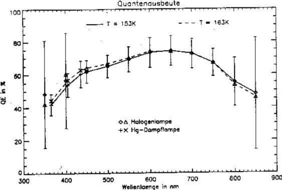
Relative Quantum Efficiency of the MONICA CCD chip
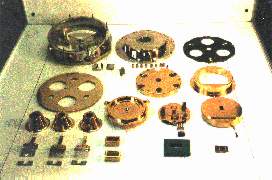
Mechanical parts of the detector head
A 68040 based VME computer is used for CCD readout and as an interface to the
motor controller and the instrument workstation.
The motor controller (Z-80 based) drives the motorized functions of
the instrument and controls the CCD chip temperature as well as that
of the filter box.
The whole instrument software is running at the VME computer.
The only link to the workstation is achieved via an ethernet cable.
The instrument is controlled via a control program from the
workstation.
In parallel it is possible to preview and process the images with
astronomical data analysis software.
The data is saved in FITS format.
Last revision: July, 2001email: Wolfgang Mitsch (mitsch@usm.uni-muenchen.de)